Tuesday, May 22, 2007

New Pictures!!

I know I promised to post how I hacked a power strip, but I did quite a bit of work on the machine today, so I thought I would post a few pictures of the progress. I will get around to
posting the power strip hack soon, I promise.


Here is the computer, test fitted to the shelf. The plan is to have a brace across the top of the computer, to hold it still when moving the arcade.


Here is the front of the cabinet with the control panel in place.
Here is the cabinet from the back. The marquee is wired in, notice the lamps.

And here is a picture with the monitor bezel and monitor plexi glass installed.
Sorry I didnt take any pictures of how we cut out the bezel and plexi glass for the monitor.
We used a black foam poster board for the bezel. It is about a 1/4" thick, and we got it at Hobby Lobby. We cut the poster board out to size, then we cut a hole to line up with the visible part of the monitor screen.
We test fitted it to make sure it fit.
We then sandwiched the bezel on a piece of wood, laid the plexi glass on top, then placed the saw board on top.
We lined up the corner of the plexi glass with the corner of the bezel, then clamped the sawboard to the bottom wood with C clamps. We lined up the edge of the sawboard with the edge of the bezel. Then using the skill saw, we cut the plexi glass. We had to do two cuts to get the plexi the same size as the bezel.
We then used another piece of scrap wood clamped to the wood, bezel, and plexi glass. We drilled 3 holes in each side to mount the bezel and plexi glass to the monitor panel.
It turned out much better than it looks in the picture. The flash from the camera made the plexi glass look cloudy.
Now we need to install the back panels.
We need to install the door hinges and latch, and the fan.
Also a brace to hold the computer still will be installed.
And I still need to wire in the coin door lights.
But first, it's off to Walmart to buy a surge protected power strip to plug the computer into. I just hope I can find one with a long cord on it.

----------------------------

Monday, May 21, 2007

I hacked my computer!

The only thing I had left to do on the control panel was to hook up the remote switch (the green power on switch).
This switch is normally open, and connects to the power switch on the computer.
You can just leave out one of the blank PCI slot covers in the back of the computer, and run the wires from the switch through it.
But I wanted to be able to unplug everything so the computer can be easily removed.
So I bought a 1/4" phono plug and jack. This plug is greatly over sized for what I need, but I wanted something that was different from all the other jacks and plugs on the computer, so that it couldnt be accidentally plugged into the wrong jack.
I also needed a plug and jack to attach the switched power strip.
This needed to be different from everything else too.
I bought a plug and jack similar to what is on power adapters.
I mounted the two jacks in a blank PCI slot cover.
Here is a pic:

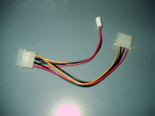
I then used a power Y adapter. This has a male and a female computer power plug, and a small plug for floppy drives.
I cut the floppy drive plug off, I dont need it.
I then cut one of the black wires and the red wire off short. I capped both with heat shrink.
The red and black are +5vdc and ground. My switched power strip has a 12 volt relay, so I dont need the 5 volt leads. I connected the yellow wire to the center terminal of the small jack, and the black wire to the outside terminal. I also soldered a diode across these wires. This is to quench the surge from the relay when it turns off. When current stops flowing through a coil, the collapsing magnetism in the coil generates a reverse current, called Back EMF. This back current can be hundreds of volts. It only lasts for a few milliseconds, but it can damage electronic semi-conductors. I doubt if the computer's power supply would be harmed, but I figure why take the chance? The diode across the leads to the relay will "short out" the back emf, thus protecting the computer. I used one of the 1 amp diodes I bought earlier. (see the load/save entry). The cathode (band) of the diode goes on the yellow wire. (Important.)


I then soldered two wires to the 1/4" jack. This will be for the remote on switch.
I then removed one of the blank PCI slot covers and replaced it with the one I had modified.
I had a spare power plug that I used for the power jack, but if I didnt have one I could have un-plugged the hard drive power plug, plugged it into my Y adapter, then plugged the other plug on the Y adapter back into the hard drive.I then cut two wires going to the computer's power switch. I connected my switch jack into the wires, soldered them, and insulated with heat shrink. This computer, a IBM Netvista, had 4 wires on the power switch. This is the first computer I have seen with more than 2 wires on the switch. There were two yellow and two blacks. I found on the internet that you can splice into either of the yellow and black wires for a remote switch.
So I picked a yellow and black, cut and trimmed them. Then I plugged up the computer and touched the two wires together for a test. The computer came on, so I then turned off the computer, unplugged it from the wall, and soldered my remote switch wires into the circuit.
I soldered the power on switch back in too, so the computer can still be turned on from the front of the computer.

I then replaced the computer's cover.
I now have two extra jacks on the back of the computer. My switched power strip and the "machine on" button on the control panel now have a place to plug into.

On my next entry, I will show how I hacked a cheap power strip to a 12 volt relay.
Note: if you try the above procedures, please make sure your computer is turned off and unplugged. A slip of the hand could short something and cause you a terrible headache.
------------------------

Sunday, May 20, 2007

Coin switch wiring diagram

Here is a schematic of how I wired the coin switches, coin cheat switches, and the cheat disable switch. Click on the picture to enlarge it. Use your browsers "Back" button to return here.


Notice how the micro switches on the coin chutes are orientated differently from the player pushbutton switches? On the coin micros the normally open and normally closed connections are opposite what they are on the pushbutton micros.
Just be sure you wire the switches you have correctly. The switches should have a marking as to which connection is what. Remember that I only use normally open switches on everything on The Rage.

Saturday, May 19, 2007

A few new cabinet pictures

Got the T-Molding installed. Here is a pic of the top part of the monitor and the marquee..
(Marquee is not powered up.)


Here is a blurred picture of the monitor. You can see the speakers in this picture. I used regular computer speakers, hacked from a cheap set. The covers are car speaker covers. They add a good look to it, I think.
I have yet to install the black bezel and plexi glass over the monitor.

Here is a picture of the speakers. Can you see the volume knob between the speakers?
The speakers are mounted in the holes I showed you earlier, held in place by 4 screws each. The covers have snap out grills. The frame of the cover is held with 4 screws. When you snap the covers on, you cant see the screws.

And here is a shot from behind the marquee. You can see the speakers, the speaker amp, and the volume control pot, which is held in place by the block of wood. I removed the pot from the amplifier board, and soldered extension wires between it and the board.
You can also see the 12 volt incandescent marquee lamps.
We decided to remove the coin door and paint it. I think it looks a lot better now.
Locks are installed now too.


And here are the coin mechs, switches are not yet wired.
And here are the coin switches wired in.
We installed a small L shaped bracket across the two coin mechs. We mounted a toggle switch to it.
This switch can be used to enable or disable the coin cheat switches.
The switch will be behind the coin door, only accessible if door is opened, requiring a key to open. The yellow cable is a 4 conductor 22 AWG cable.
The coin slot lamps are not yet wired. They will be wired to the 12 volt power supply.

Here is the cable going to the bottom of the control panel cavity. It is attached to a terminal strip and wired into the coin cheat switches. I decided to use terminal strips so that the control panel can be completely removed, if ever need to. I used staples to fasten the cable up out of the way.
Here is a shot of the coin cheat buttons, wired into the terminal strip. (Terminal strip is on the left, hard to see in this pic.) The other terminal strip is for the trackball light. it will have 12 volts wired to it. (Sooner or later.)

Next is a shot of one of the monitor braces. We put a small block on each side of the monitor, to keep it from moving sideways.
The front of the monitor sticks through a hole cut in the monitor panel. It fits snug.
The shelf the monitor is sitting on has a brace beneath it, to keep the shelf from bowing under the weight of the monitor. I removed the tilt and swivel thing that the monitor ordinarily sits on. We didnt need it on this project. It was easily removed.

Next is the top brace. It goes across the top of the monitor, and wedges against the flared out part of it. This keeps the monitor from sliding back away from the monitor panel.
There are also two L brackets on the very top of the monitor. I attached them to the monitor using screws in existing air vent holes. I made sure nothing was inside that the screws could touch.
The L brackets keep the monitor from sliding towards the front of the arcade.
I wont touch a lot on how I mounted the monitor. Each monitor is different. it may be shaped different, or be a different size. Just think about how you are going to mount your monitor, and make sure it is held securely in place. And remember, most monitors are heavy, so support the shelving so that it will hold the weight for a long time. Remember also that the monitor needs to "breathe" so allow air space around it and try not to cover too many air vent holes.

Here is the front bottom part of the monitor. I cut out the monitor panel to allow access to the controls. These will be covered up with the monitor bezel, but if the monitor should ever need adjusting, it shouldnt be a big deal to remove the bezel to get to these controls.
The bottom part of the monitor had a recessed area under the controls, this worked out good, it keeps the monitor from sliding forward on the bottom.
The power button was in this recessed area, so i bored a hole to allow me to insert a pen to turn it on, if I need to. (I will have to plug the monitor up and make sure it is turned on before installing the bezel.) The monitor switch we be on all the time.


There will be a space between the upper-back panel and the back-top panel. This is to allow heat to exit the cabinet.
We used nylon screen wire to keep dust and bugs out. When we first installed it, it sagged in the middle, so we had to install two braces for it to staple to.
When both panels are installed, there will be about a 2 inch wide opening across the width of the machine. This screen will be behind the panels and across the opening.
This opening should be sufficient to allow the hot air to escape. (The fan at the bottom of the cabinet will help a lot too.)
Now, I need to cut out the monitor bezel and monitor plexi glass.
The control panel is ready to mount, but since the edge of it will be in front of the monitor's plexi glass, that plexi glass will have to be installed first.
I am working on the computer, installing necessary software. It is just about ready.
I have also been working on the switched power strip. (More on that later).
So everything is really starting to come together now.
--------------------------

Thursday, May 17, 2007

Game load and save

Mame has an option that allows you to load and save games.
From the keyboard, pressing SHIFT and F7 allows you to save a game to a location.
The location can be just about any key on the keyboard, except player one controls.
Pressing just F7 by itself allows you to load the game back in from the location it was saved to earlier.

This is a pretty nice option, but it does have a few drawbacks.
First, it doesnt work with all games, but it does work with most.
Second, you have to remember which button you saved the game to. A way around this is for each player to pick a certain button (such as player 1 start) to keep his (hers) game at, and keep this selection.
Also, if someone saves the same game to the location (button) you picked, your saved game will be over written. But different games can be saved to the same location.
But it is neat to be able to save games. I have thought this since the early 90's, when I saved my progress with Doom and Duke Nukem. (Ahh, the classics..)

So I decided that The Rage would have a save and a load button.
This is my first machine to have this option.
The problem I had to solve was how to do this.

The keywiz keyboard encoder has an input for the left shift key.
This is also the player 1, action button 4.
But the encoder's default mapping does not include the F7 key.
I got around this by downloading a program called "The Keywiz Uploader".
This program is a free download and is available from the groovy game gear website.

The Uploader allows you to change the key map of the encoder.
I re-mapped the "H" terminal from the default "L" to "F7".
I then connected the "H" wire from the encoder to the "Game Load" button on the control panel.
So to activate the load function, all you have to do is press the "Game Load" button.
But how to use the save game function?
Well, I accomplished that by wiring the "Save Game" button to both the player 1 action 4 button (shift) and the "Game Load" button (F7).
I used diodes to block the signals so that pressing player 1 action 4 button doesnt open the save or load functions.
A diode blocks current flow in one direction, but allows it to flow in the other direction. Think of it as a one way check valve.

Here is a diagram of how I hooked it all up:

Pressing P1 Action4 button connects terminal 4 of the encoder (left shift) to the ground, activating the left shift input. Diode 1 blocks the current flow from the other switches.
Pressing Game Save Button allows current to flow from ground, through Diode 1 to the Left shift input. The current also flows through Diode 2 to activate the F7 input. This has the same affect as pressing the left shift key and the F7 key. (This activates the save game option).

Pressing "Game Load" button connects the ground to the F7 input.
Diode 2 blocks the current flow from the left shift input. So this has the same affect as pressing only the F7 key. (This activates the game load option).

Just about any general purpose diode should work. I used 1-amp rectifier diodes from Radio Shack.
I bought a pack of 25 assorted 1-amp diodes, Radio Shack # 276-1653.
-------------------------------

Wiring up the control panel

I first marked, on the wiring side, all the buttons, to keep me from getting confused. I also marked U, D, L, & R on the micro switches of each joystick. You have to be careful here, because the joystick orientation is backwards from the front side of the control panel.
I then mounted the keywiz eco2 keyboard encoder. The keywiz is very small, which is good when the control panel is as crowded as this one.
I positioned the encoder so that the IDE cable will plug in to easily run left and right of the control panel.
I also had to leave room for the PS/2 cable to plug into the encoder.
I mounted the encoder to the wood using small screws. I used rubber grommets as spacers, to raise the encoder off the wood. This may not be necessary, but I didnt feel good about having the electronic circuit board resting on the primed wood.

I then ran ground wires to each switch (except the mouse clicks). I used #20 AWG stranded copper wire.
I used two ground circuits. One for each side of the board.
I could have used just one circuit for all the switches, but the keywiz has 3 ground connectors, so I thought it might keep the wiring a little neater to use two ground circuits.
Notice how the ground wire just "daisy chains" to each switch.
Also, on the bottom left side, you see a wire going off the board. This will pick up the coin credit switches.

I then connected the IDE cable to the encoder and separated the wires as I needed them.
I soldered the ground wires first. I marked each wire as I singled it out from the group.
I used the same markings that the encoder has stamped on it.
I used peel and stick marker tape (Available at electrical supply house.)

I connected the IDE cable wires to the COMMON connector on each switch.
I am an electrician, so I automatically think that the common wire (the black ground wire in this project), should connect to the terminal marked "Common" on the switch.
But on these switches, the common is on top, and since the switch doesnt care which way it is wired, I attached the ground wire to the Normally Open contact on the switch.
This left the Common contact easier to get to when I soldered the small IDE wire to it.

After I connected all the switches, I soldered the wires from the mouse board to the mouse click buttons.
Here is the finished result:
What a bird's nest! (I did straighten up the appearance a little later.)
I still need to solder two wires to the "power on" switch (green button).
These wires will go back to the computer to turn it on.

Some notes about the IDE cable:
Use the older type 40 wire cable. Even though an 80 wire cable will probably work, the wires for this type cable are very small, and will be harder to work with.
You will need a fairly long one. I happened to have a 2 foot one in my junk box, which worked out pretty good.
If the one you have is not long enough to reach all the switches, you can splice wires to them to make them long enough. But having the wires to reach all the switches without splicing, cuts down on the work. I will need to splice two wires for the coin switches, but I can live with that.

If you look close at the bottom picture, you will notice a white wire in the bunch.
Also two diodes on the top left button switches.
I used this for the game save/load circuit.
More on that later.
-----------------

Interfacing the trackball

As I mentioned earlier, I needed to use a PS/2 mouse to interface the trackball to the computer.
I bought a cheap mouse off the net at Geeks.com
Here is a picture of the mouse, with the top removed.


I then removed the circuit board. (The rest I threw in the garbage.)


I then removed the led emitters, the receivers, and the micro switches that the mouse buttons activate. This mouse has a plug on the cord that plugs into the circuit board, I unplugged it to make the operation a little easier. I used a soldering gun and solder wick to un-solder the components. The solder wick is pictured above the mouse components.
This mouse didnt have a scroll wheel, so there are only two led emitters and two receivers.
These parts are below the solder wick, also the two micro switches.
I then soldered two wires into the holes in the board where the receiver's outside leads soldered to, for a total of 4 wires that will attach to the trackball.
I then found the 5VDC points on the board and soldered two wires to those.
I then soldered 2 wires in the holes that the mouse button switches were in, for a total of 4 wires which will attach to the mouse click buttons on the control panel.
I wound up with 10 wires coming from the mouse board.
I then attached the receiver wires to the green, blue, yellow, and purple wires of the trackball.
Then I attached the 5VDC wires to the red and black wires of the trackball. This supplies the trackball with the power it needs to work.

I then re-connected the mouse cable to the board, plugged it into the PC and tested it.
The mouse arrow (on the computer screen) has to move up and down and left and right when you move the trackball.
It it doesnt move in sync with the trackball movements, you will have to swap the 4 receiver wires around until it does move right.
After it tested OK, I soldered all connections and insulated with heat shrink tubing.
I then attached the board to the trackball by clamping the mouse wires with a plastic clamp.
I also used a plastic wire tie to hold the mouse board to the trackball LED board.
Here is a pic.

I know this is very sketchy. I may go more in depth with the mouse hack later.
If you want to hack a mouse, search for how to do it on the web.
I also suggest that you read up on how a mouse works, so that you will understand what is going on.
I have also found that not all mice are suitable for hacking to a trackball.
The receivers have 3 leads. For the mouse to work, each outside lead of the receiver must go back to a pin on the integrated circuit (chip) on the mouse board.
I have found some mouse boards where the center lead goes back to the chip, and the outside leads go to power + and -. These chips will not work.
If you turn the circuit board upside down and follow the traces you can tell how the receivers connect. I think that a chip with the number 361125-0000 (made by Logitech) will not work. I cant find any datasheets on this chip, but it looks like to me that the recievers have only one lead going back to the chip.

Before you hack the mouse, I highly suggest that you study the way the receivers wire up.
You can get the number off the chip and search for a datasheet on the web.
A datasheet should tell you how the chip connects to the receivers.

Here is the number on the chip that I used:
(Genius) k0307057 2k337b13
I also have this chip and plan to use it on my next hack, Im pretty sure it will work:
ec3592re (probably generic, I cant find a manufacturer name).
This is the chip in the pictures above. I bought 3 cheap mice for hacking.

The mouse does not need a scroll wheel, but if it has one, just unsolder the emitter for the scroll wheel, dont unsolder the receiver or the micro switch for the scroll wheel.
I would leave the scroll wheel receiver in the board, just to prevent the chip from receiving any false noise signals. I would unsolder all the emitters, just to cut down on the total current draw, because the trackball will draw some, and Im not sure how much current the computer's PS/2 mouse connector is good for.

Like I said earlier, I may go more in depth on how to hack a mouse.
But for now this should give you an idea of what I had to do.
---------------

Sunday, May 13, 2007

Lighting the trackball

The trackball Im using for The Rage has a translucent ball, which means the ball can be lit.
The light source mounts to the bottom of the trackball. A hole in the bottom lets light through, to make the ball glow.
This is a really cool effect, and if you can afford the extra cost, get one for your arcade. (Its really not that much more expensive, and well worth it, in my opinion.)

The trackball came with a 12 volt incandescent bulb and socket, but I used that on the marquee, so I had to come up with a different light source.
I used a jumbo red LED. I used red because thats the only color Radio Shack had at the time.
The ball is orange, so the color of the ball with the LED illuminating it is a reddish orange. It doesnt look bad at all.
The LED is a Jumbo Super bright, Radio Shack number 276-086.
It is rated for 40 ma max current, so to use it with my 12 volt supply, I selected a 330 ohm 1/2 watt resistor, to limit the current flow through the LED.
Using Ohm's Law, I=E/R, or Current (I) = Voltage (E) divided by (/) Resistance (R)
The LED drops about 2.4 volts, so I subtracted that from my supply. (12 volts -2.4 volts =9.6 volts).
So, 9.6/330 = .029 amp, or 29 ma. (result rounded.)
This is well below the maximum current of the LED, so I should be ok.
The LED is very bright. It is uncomfortable to look directly at the end of it.
I mounted the LED and the resistor to a small piece of perfboard (also available at Radio Shack).
I then attached a piece of speaker cable to the LED and the resistor. The speaker cable will be the wires that will tie into the 12 volt supply.
Here is a picture of the finished board:

The board will mount to the bottom of the trackball. The LED will shine into the trackball through the hole in the bottom of the trackball.
The LED looks clear, but it glows red.
The hole at the end of the perfboard will be used to mount the perfboard to the trackball.

Here is a picture of the LED powered up.


And here is the end result, pretty neat huh? (It looks a lot better than this picture.)


I didnt get a good picture of the the perfboard mounted to the trackball, so I drew a rough sketch, which should give you an idea how it's done.

At the bottom of this sketch is the electrical schematic of how the resistor and LED hook up.
I wired the LED, the resistor, and the speaker wires by twisting their leads together and soldering. This method is called point-to-point wiring.

The circuit must be hooked to the power supply as shown. It wont hurt anything if I hook it reversed polarity (backwards), it just wont work.
So when I hook it to my power supply, if it doesnt come on, I will just reverse the wires.
(One of the speaker wires is marked with a red tracer, I'm using that one for the positive, just so I get it right the first time.)

If you have any questions, just email me. I'm no expert, but if I can help I'll be glad to.
email: kenrager@hotmail.com
-----------------------------

Friday, May 11, 2007

About the switches

I thought I would touch on the switches for a minute.
Each pushbutton has a "micro switch" that is removable.
Each joystick has four of these micro switches each.
The Joystick switches are not easily removable, and they have a "paddle" on them.
The paddle pushes the plunger on the micro switch, so all the switches wire the same way.
Each micro switch has a common contact, a normally open contact, and a normally closed contact.
Here is a diagram I drew to help explain the way the switch works.
Just keep in mind that even though the pushbutton switch and the joystick look a little different, they work the same way.


I will be using the Common contact and the Normally Open contact. The normally closed will not be used on any of the switches on this control panel.
The mouse click buttons look a lot different from the micro switches, but they work the same way. Except they have only a common and a normally open contact. (Just two connections).
----------------------

Thursday, May 10, 2007

Control panel is shaping up

Got some work done on the control panel.
Mounted both joysticks, all the buttons, and the trackball.
I printed out several arcade characters. I also made up some labels for the buttons.

Here is a pic of the panel before mounting trackball..


And here is a close up of the right side..


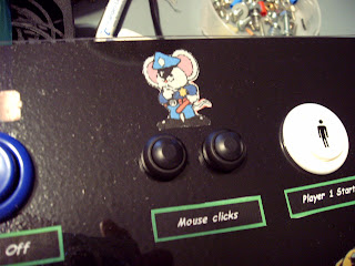
Here is a close up of the mouse click buttons...
The label got a little crooked, not sure how.
I used a glue stick to attach the pictures and labels to the wood, then the plexi glass should hold them, but somehow this label got a little off. Got to decide now if it is bad enough to tear everything down to fix it.


Here are the mouse click buttons, before mounting them. I got these buttons from allelectronics.com


Here is a pic of the controls, ready to be wired.
I still have to mount the keywiz eco2 keyboard encoder, then I can wire all the buttons.
The "machine on" button (green) will not be wired into the encoder. It will wire directly to the computer to turn it on.
The mouse click buttons will not wire to the encoder either. They will attach to the mouse hack.
I stated earlier that I will hack a mouse for the trackball. Actually, I had already hacked a USB mouse for this trackball, but I found that the computer I am going to use gives an error on bootup if it doesnt see a PS/2 mouse, so I am going to hack a PS/2 mouse. I plan to document that when I do it.
I could have disabled the error in BIOS, but the computer still has to completely boot up before recognizing the trackball, so I will just re-hack it to a PS2 mouse.
I also need to attach the LED to the trackball to light it up. more on that later.


Here is a close up of the joystick mounting method I used. Thought you might like to see how it turned out. I am leaving the handles out of the joysticks until the wiring is finished. It makes it somewhat easier to lay the control panel on its front without the handles in the way..
Notice also the way I had to counter sink the nuts for the trackball..
(Right behind the joystick in this picture.)

I used 8/32" bolts and nuts to mount the joysticks. (1-1/4" long, available at Walmart.)

Now, I got to mount the keyboard encoder and get out the soldering gun!
------------------------------------

Monday, May 7, 2007

Update...

Got the coin door mounted today. here is a picture. (Picture is not real good.)


Here is a picture from inside the cabinet.
Notice the small brackets around the edge of the coin door? This is what holds the coin door to the panel.
The braces on the sides of the cabinet are for the computer shelf.
Im not sure if you can tell in this picture, but one of the coin mechs is missing. I have it, just havent installed it yet.
Got to get some locks too.


And here is a picture with the computer shelf installed. The computer will sit on this shelf.
Notice the cutout for the coin door mechs.
The cabinet fan will mount in the back door, below this shelf.
The space around the shelf will allow air from the cabinet fan to blow around the computer, to remove the heat generated by the computer.

Also got the control panel painted.
Here is a picture of it with the first coat of paint:

The panel got two more coats of paint. I will let the paint on the control panel dry overnight.
It is very important that the paint be dry before placing the plexi glass on it. The plexi glass will adhere to sticky paint, making it hard to remove if necessary.
(Hopefully that wont ever be necessary.)
Next I will place the plexi glass then mount joysticks, trackball, and all the buttons.
Then the fun part of wiring it all into the keyboard encoder will start.
But before I can mount the trackball, I will have to hack a mouse and connect it to the trackball.
You can buy trackballs with the computer interface already on them, but the one I got from EBay does not have the interface, so some unlucky mouse will be hacked to death, or maybe just "assimilated" into the trackball!!
-----------------------------------

Sunday, May 6, 2007

Switching the power

WARNING: working with 125 volts can be dangerous.
Please do not attempt to do this if you do not fully understand what you are doing.
I cannot be held responsible for any mishaps, fires, damage, or personal injury.
Working with electricity can either be safe, or extremely dangerous, depending on what you do with it and how you do it.


I have been asked, how do I turn everything on and off on the arcade?
I have used a fairly simple approach since my first machine, Benny B's Arcade.
Well, it's simple if you know a little bit about electricity. If you dont know anything about electricity, dont let it scare you. Its really not that complicated.
The idea is to have everything else come on when the computer is turned on, then everything turn off with the computer turns off.
Everything else means the monitor, the marquee lights, the coin door lights, the speakers, and the cabinet fan.
At this stage of the project, you have to look at the arcade machine as a computer, because really thats all it is. When you turn on your computer, the monitor has to be turned on, then the speakers.
You probably do this on your home computer by stepping through the power buttons.
But on an arcade machine, we want to be able to do all this with the press of one button. But not only do we want the monitor and speakers to come on, but also the marquee light, the fan, and the coin door lights.
In earlier times, people used a computer running only DOS operating system.
The computer used what was called an AT power supply. If you have had a computer 10 years or so ago, you might remember that you had to turn the computer off after shutting down Windows. (The message "It is safe to power off your computer" would pop up after quitting Windows). This was a computer with an AT type power supply.

On these earlier home arcade machines, you simply turned on and off a switch (usually in the back of the cabinet, out of sight). The computer, the monitor, and everything else was wired through this switch. Turn the switch on, the computer booted up and everything came on. Turn the switch off, everything turned off.
This worked great for those setups.
And this may be the way you want to go.
Here is a diagram I drew to help explain how you would do this, if you chose this route:

You can click on the picture to enlarge it, press your browsers back button to get back here.
With this setup, you use an ordinary surge protected power strip (SPS), which the computer and everything else plugs into.
You cut the cord of the power strip, tie the white wires back together, and the green wires back together. You then tie the black wires to a toggle switch, which is mounted somewhere on the cabinet.
Turning the switch on turns on the power strip, turning it off turns off the power strip. Anything plugged into the power strip will then be controlled by the toggle switch.
In this setup, the toggle switch MUST be rated for at least 125 volts AC, and it also must be rated for at least 10 amps. The power strip needs to be a surge protector type (to protect the computer against incoming power surges).
When the white and green wires are connected (spliced), they need a good tight connection. Best is twisted, soldered, and heat shrink tubing (or electrical tape) applied for insulation. Next best method is to use insulated butt splice crimps. You could also use "wire nuts", but if these are not installed correctly, they could create a problem later.
The black wires need to be attached to the switch by soldering (best) or crimp terminals.
All connections need to be tight and well insulated. A loose connection will create heat, which is a definite no-no. A poorly insulated connection may short out, causing sparks, or be a shock hazard. If you dont feel good about doing this, get someone who is experienced to give you a hand.
An alternate method would be to buy a power strip that has a switch already on it, then mount it where you can get to the switch to turn it off and on. (No splicing the wires necessary.)

The above method works great, if you are using an older type computer for your arcade.
But most computers nowadays use what is called an "ATX" power supply.
These computers shut down automatically when you quit Windows.
This is the type computer I will be using for my arcade.
Even though you could still use the above procedure to turn off your arcade, you will need to press the button on the computer to turn it on. Plus, Windows doesn't like you to shut down the computer by turning off the power.
What I wanted was two buttons on my control panel, one to turn everything on, and another to shut everything down.

So I came up with two power strips, one is a surge protected strip. The computer plugs into this one. Another power strip (a cheap one that is not surge protected) also plugs into the surge protected strip. The cheaper strip is wired with a 12 volt relay to turn it off and on.
Look at this diagram:As you can see, I am switching the black wire of the power strip (PS) with a relay.
This relay has a 12 volt dc coil, and 10 amp normally open contacts. The monitor, fan, and everything else plugs into the power strip (PS).
The surge protected power strip (SPS) only has the computer and PS plugged into it. It is powered on all the time.
The coil of the relay is powered by 12 volts from the computer. It is attached to the black and yellow wires inside the computer that plug into the hard drive, the floppy drive, or the cd rom drive. (More on how I made these connections later.)

To be able to turn on the computer, I wired a normally open pushbutton (PB1) that is mounted on the arcade's control panel, to the "power on" switch inside the computer. This is the button on the front of the computer you would normally press to turn on the machine. On most computers, this button only has two wires. You simply splice into these two wires. (More details later).

The way this works is extremely simple.
When you turn on the computer by pressing its power on button, the power from the computer's power supply turns on the relay, which turns on PS, which powers up everything plugged into it. Shutting down the computer turns off the relay, which turns off everything plugged into the PS power strip.

The relay must have a 12 vdc coil, and its contacts must be rated at least 125 volts ac, with at least 10 amps of current. Also, all the connections must be tight and insulated. Radio Shack sells a relay which works good. If you dont like to solder, pick up some crimp connectors for it too. (The people at Radio Shack should be able to tell you what you need.) The relay must have at least one Normally Open contact. This is the only contact on the relay you will need.
Relays are also available from many sources on the web.

I used a small relay that I attached right to the power strip (PS). I may talk more about that later, but this should give you an idea of one way to do the power switching.
An alternate method would be to use a relay with a 5 volt coil, then plug the relay into a USB port. I haven't tried this, but it should work just as well, and you wouldn't need to splice into the computer's power supply wires.

WARNING: working with 125 volts can be dangerous. Also letting the 125 volts come into contact with the 12 volts can fry your computer's power supply.
I cannot be held responsible for any mishaps, fires, damage, or personal injury.
Working with electricity can either be safe, or extremely dangerous, depending on what you do with it and how you do it.

Now, how do I shutdown the machine with a button on the control panel?
Well, if the computer you are using lets you shut down your computer by pressing the power button, you can simply press PB1.
But Windows may not like this, and not all computers are capable of doing this.
So I wired another button, (mounted on the control panel) into the keyboard encoder that sends a button press to the computer.
My computers "front end" is set up to exit if it sees a "C" pressed.
There is also a button to quit a game, this sends an "ESC" to the computer. But this only exits the game and returns to the front end.
When the front end exits (by pressing "C"), I have a program that automatically shuts down the machine.

This program, called "The Launcher" was written by me and is available as a free download.
The Launcher is set up by you to start your favorite front end when the computer boots up. It waits in the background until it senses that you have exited the front end.
It then pops up a "shutdown screen" (which can be designed by you), that tells you the arcade will shut down in so many seconds. During this time, a special key on the keyboard can be pressed to cancel the shutdown, in case you want to return to Windows and do maintenance on the computer, install new games, whatever.
If the button is not pressed before the countdown reaches zero, The Launcher will shutdown Windows, power off the computer, and the relay will turn everything else off.

Here is the link to The Launcher, feel free to use it if you want:
http://skennys_outpost.tripod.com/thelauncher/index.html

The Launcher requires Windows 98 or better, and an ATX type computer.
There are other methods to shut down your machine, but the method I have just discussed works great for me. Just google search and see what you can come up with.

Note: The above wiring diagrams are for 125 volt AC, which is common in the US.
European systems which use 220 volts, may wire differently. But the concept is the same.
Just make sure the relay contacts or the switch contacts are rated for your voltage and current.
Above all else, be safe!
---------------------------------------