Monday, July 9, 2007

The Rage goes home!!

Moving day is here! This is a picture of The Rage loaded onto the Mighty Dodge!
We wrapped the arcade in old sheets, to prevent scratches, then we strapped a two wheeled dolly to the arcade, loaded it on the truck, then wrapped it all in plastic, just in case it rains..


We fastened the machine to the truck with 2X4's bolted to the bed rail, and ratchet straps.
We didnt have room for the plywood ramp, so we bolted it across the bed directly behind the arcade. Some well placed cloth strapping and the all powerful duct tape, and we are ready to hit the road.


125 miles later we got The Rage unloaded, unwrapped, and placed in my son, Kenny's living room.


Notice the look of astonishment on Kenny's face!


Here is Kenny and his friend Kyle trying it out.


And here is The Rage, placed in the corner blocking the front door. (Who needs a stinkin' front door anyway??)
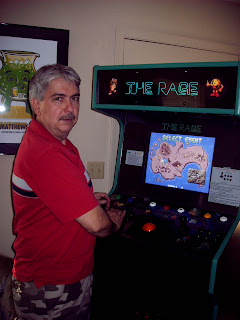
And yep, that's me, Dear Ole Dad, testing it. (Somebody pass me the Tylenol for my back.. this machine is HEAVY!!)


And Kenny, happy as a cat in a bird house...


And that my friends, is what makes all this hard work worthwhile!
If you decide to build an arcade machine, good luck, and have fun!!
--------------------

Saturday, June 16, 2007

Some more pictures

Just a few more pictures of The Rage.

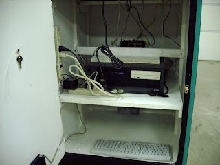
Looking through coin door, back of computer with keyboard and a memory stick plugged into USB ports.
Green plug: Trackball
White plug: Keywiz keyboard encoder.
Black plug: Keyboard plugged into usb port.
Blue plug: monitor VGA plug.
Black illuminated memory stick plugged into usb port.
Light green plug: speakers.


Front end (Glaunch)

Control panel underneath.
Power strips. Notice L Bracket at bottom front of computer, I installed 4 of these to hold computer in place during transporting.


The fan (120 VAC)

Back door open, notice bottom space used for storage of keyboard. Coindoor keys are stored on back door. (Tie wrapped to hold while transporting arcade.)
Back door opens to allow access to CD drive and floppy drive.


Back of marquee, looking through vent opening.
I used rubber weather stripping around marquee to block light from getting through small space around marquee.

--------------------

Friday, June 8, 2007

It is finished!

If this is your first visit here, I highly suggest you use the menu at the right to start from the beginning and go through all the steps. This post is the last one. "Alpha" is the first.

Well, the project is finally finished. The Rage was my third machine, and it was fun.
I also learned a few new tricks.
Using the sawboard is a definite have-to-do from now on out.
Cutting out pieces of MDF to use for the frame works out better than using 2X4s.
Creating the marquee was fun too.

This machine was built for my son's 24th birthday (which means this is about 3 months late).
My son lives about 100 miles from me, so as soon as our schedules allow, we are going to load up The Rage and take it to it's home. (Looks like a job for The Mighty Dodge!)
Maybe we will get more pictures of that adventure.

But for now, here are pictures of the finished product:
Side View


The Marquee


Back View


Front view

Control Panel


Computer


Coin door opens to gain access to back of computer, to plug in keyboard, etc.


Thanks to my brother for helping me on this project, and for letting me use
The Busted Knuckle Garage.
-------------------------------------------------

Coin Door LEDs


Ok, I switched out the two power hungry incandescent lamps on the coin door with two bright LEDs. The LEDs are 5mm Yellow 720 mcd, available at Radio Shack (#276-350).
The LEDs are rated for 20-30 ma, so I needed a resistor. I figured it for 20 ma.
The forward voltage on the LED is 2.1, so I subtracted that from my power supply of 12 volts.
Using OHMs law:
R=E/I
R=resistance in ohms (This is what I need to know)
E= voltage (12-2.1= 9.9)
I= current (0.020)

E/I= 9.9/0.020= 495
R= 495

The closest resistor I had was 470, that figured out to be 0.021 amp (21 ma) which is just fine.

I soldered the resistor to one lead, and covered the connection with heat shrink. I then trimmed a small red wire and slid the insulation over the other lead.
I then soldered the LEDs to the coin doors lamp holder leads.
Here is a picture:
The picture is a little blurred, but the LED leads bend around to either side of the lamp holder, then soldered to the leads at the back of the holder.
The LED is positioned center of the lamp holder, where the bulb would usually be.
I then slid the holder back onto the mount.

Here is a picture with both LEDs in place. (Why cant every picture be this clear?)The LEDs can be easily removed by cutting the leads to them, then placing the regular incandescent lamps back in the holders. But if that happens, a bigger wall wart will have to be used.
With the LEDs in place, the total load (Marquee and trackball included) is 0.500 amp, the wall wart is running cool now.
The picture at the top of this post is with the LEDs turned on.
The LEDs are not as bright as the incandescent lamps, but they still have a warm glow to them. I think they will be just fine.
----------------------

Thursday, June 7, 2007

Software structure

Ok, thought I would take a minute to detail the software being used on The Rage.
The OS (Operating System) is Windows XP.
On bootup, after Windows loads, a program called "KeyWiz Uploader2" starts.
This uploads the key map to the KeyWiz keyboard encoder. This is only necessary because I am changing one of the default keys to F7 for the Load and Save buttons.
Once the keywiz is programmed (about 10 seconds), the Uploader2 starts The Launcher.
The Launcher then starts GLaunch.
From GLaunch, Mame games can be run.
Also from GLaunch, MenuMaker, WinCab Jukebox, RomMan, and GLaunchMan can be run.
When the blue button is pressed while in GLaunch, GLaunch exits and The Launcher gives you the chance to go into Windows to do housekeeping, or it will shutdown the machine.

Here is a description of each program listed above:

Windows XP: Operating system that came with the computer.

KeyWiz Uploader2: Programming utility for KeyWiz keyboard encoder.

The Launcher
: a utility program written by me.

GLaunch: A Front End menu program to list all your games.

MAME: Multiple Arcade Machine Emulator. This program runs the arcade games.

MenuMaker
: This is a program I wrote to allow me to create Favorite Games lists for GLaunch.

WinCab Jukebox: A pretty neat little program that will play your MP3 music like a jukebox.

RomMan: This is a program I wrote that allows me to test a rom before adding it to my collection. I haven't got this program ready for downloading yet, so it's not available to the public, YET.

GLaunchMan: This is another program I wrote to allow me to manage GLaunch game lists.
It allows me to test the rom in question, remove it from the list if it is bad, change the roms description displayed by GLaunch, or add new roms to the GLaunch list.
It is not ready for download yet.

Roms: You might ask what are Roms? Roms are the actual game files. Mame runs a game by opening the games rom. The rom contains all the files needed to emulate and run the game.
The rom is in zipped form. Example: Pacman.zip.
The roms are stored in a folder called ROMS, located in the MAME folder.
Although all the programs I have listed above (except WinXP), are free downloads, most of the Mame Roms are not. Someone most likely owns the copyright to the game rom.
I think the rule is that if you own the actual circuit board to a game, then it is ok to have the rom of that game.
That being said, I will not post any places where you can get the roms, and please don't ask me to. But you can probably find sites that offer free downloads on the internet, I just wont be able to help you find them.

Note: The above links are to websites that are not managed by me. I cannot be held responsible for any mis-information or content on the sites, or if the sites are updated or maintained.
The MenuMaker and The Launcher sites are maintained by me, so any questions about those sites should be addressed to me.
--------------------

Almost finished!

I have everything installed, and have touched up some scratches in the paint job.
Everything is looking good, except for one small problem.
I am using a 12 VDC 1 amp power supply for the marquee, trackball light, and coin door lights.
The power supply (a plug in type commonly called a "wall wart"), is getting very hot.
A temp probe I have on my multimeter measures it at 110 degrees F.
I'm afraid it wont be long until the wall wart burns out, plus it is like a little heater, adding heat to the inside of the cabinet.
I cut one of the wires on the wall wart and put my amp meter in line with it.
The total current draw is .974 amp (974 milliamp). This is too close to the 1 amp rating of the power supply. I removed the coin door lamps and the current dropped to around .450 amp.
The wall wart cooled down quickly.
So, I have decided to replace the incandescent coin door lamps with LEDs.
The LEDs will draw about .020 amp each, so this should be OK. Plus they will outlast the incandescent lamps by several years.
But I am worried about how they will look.
I will post more on this later, plus some pictures of the finished cabinet.
--------------------

Sunday, June 3, 2007

Power strip hack

Ok, Its been awhile since I posted. The job that pays me to be there required that I be there.
(Why cant they just mail me my check?)
I promised earlier that I would post how I hacked a cheap Power Strip to get my Switched Power Strip.
I picked up a cheap power switch from Walmart. This power strip is cheap because it is not surge protected. This strip has a breaker switch mounted to it. This is really not necessary, but I left it on this strip. On the strip I hacked for The Rage, I removed the breaker and mounted the relay in the hole where the breaker was mounted.
This strip had plenty of room behind the breaker, so I decided to leave it.
The relay has a 12VDC coil, and it's one normally open contact is rated for 10 amps and 250 VAC.
I found it on the Internet, bought 5 of them. The way it is shaped makes it perfect for this project.

I removed the six screws in the back of the power strip and gained easy access to it's insides.
See the black wire is soldered to the breaker switch, this is the wire I will cut and solder to the relay.


I then pulled the cable back and flipped the strip back over. Using the relay as a guide, I marked each corner.
Then using a straight edge, I "connected the dots" to give me a cutting pattern the same size as the relay.
I then used my soldering gun, with a cutting tip, to cut out the hole.

And here is the hole cut out. The soldering gun left a rough cut, but that's OK.

Next I inserted the relay into the hole. I put the connection tabs in first.
The hole was a little bit too big, you can see a space in front of the relay, but that's OK, I will fill in the gap with silicone caulking.
I then cut the black wire and trimmed both ends. The relay contact tabs had a small hole in each. I drilled these holes bigger so I could stick the black wires into the tabs. I then bent the wires around the tabs, and soldered them.
You will need a hot soldering iron to do this, these connections need good solder joints.
I then soldered two wires to the relay's coil contact tabs.
I used speaker wire on The Rage, but I was out so I used some single conductor wire I had laying around. I twisted the wires together and put small sections of heat shrink tubing to keep them together. I put heat shrink over the coil tabs to insulate them.
I then pushed the coil wires through the gap in front of the relay. I positioned the green wire in the center of the relay, the white wire to the top side of it, made sure all the outlet buss bars were properly placed, then I put the cover back on the strip.
I then soldered the coil wires to a plug I will be using to plug this switched strip into my computer.
I then filled in the gap around the relay with silicone caulking, put a plastic wire tie around the body of the relay to hold the coil wires in place.I tested the strip by plugging it into a wall outlet (None of my house circuit breakers tripped, so thats a good sign.)
I then connected the coil plug to a 12 volt power supply. (The relay clicked, another good sign.)
I then plugged my waffle iron into the power strip. I applied 12 volts, the waffle iron came on, I removed the 12 volts, waffle iron went off. The waffle iron is rated at 650 watts, so I figured it was an excellent test load for this strip. I don't think the total load will be that high on this strip when it is in the arcade.
And this my friends, is how I hacked a poor defenseless cheap Walmart power strip to do a lifetime of servitude as a arcade machine part.
-----------------------

Tuesday, May 22, 2007

New Pictures!!

I know I promised to post how I hacked a power strip, but I did quite a bit of work on the machine today, so I thought I would post a few pictures of the progress. I will get around to
posting the power strip hack soon, I promise.


Here is the computer, test fitted to the shelf. The plan is to have a brace across the top of the computer, to hold it still when moving the arcade.


Here is the front of the cabinet with the control panel in place.
Here is the cabinet from the back. The marquee is wired in, notice the lamps.

And here is a picture with the monitor bezel and monitor plexi glass installed.
Sorry I didnt take any pictures of how we cut out the bezel and plexi glass for the monitor.
We used a black foam poster board for the bezel. It is about a 1/4" thick, and we got it at Hobby Lobby. We cut the poster board out to size, then we cut a hole to line up with the visible part of the monitor screen.
We test fitted it to make sure it fit.
We then sandwiched the bezel on a piece of wood, laid the plexi glass on top, then placed the saw board on top.
We lined up the corner of the plexi glass with the corner of the bezel, then clamped the sawboard to the bottom wood with C clamps. We lined up the edge of the sawboard with the edge of the bezel. Then using the skill saw, we cut the plexi glass. We had to do two cuts to get the plexi the same size as the bezel.
We then used another piece of scrap wood clamped to the wood, bezel, and plexi glass. We drilled 3 holes in each side to mount the bezel and plexi glass to the monitor panel.
It turned out much better than it looks in the picture. The flash from the camera made the plexi glass look cloudy.
Now we need to install the back panels.
We need to install the door hinges and latch, and the fan.
Also a brace to hold the computer still will be installed.
And I still need to wire in the coin door lights.
But first, it's off to Walmart to buy a surge protected power strip to plug the computer into. I just hope I can find one with a long cord on it.

----------------------------

Monday, May 21, 2007

I hacked my computer!

The only thing I had left to do on the control panel was to hook up the remote switch (the green power on switch).
This switch is normally open, and connects to the power switch on the computer.
You can just leave out one of the blank PCI slot covers in the back of the computer, and run the wires from the switch through it.
But I wanted to be able to unplug everything so the computer can be easily removed.
So I bought a 1/4" phono plug and jack. This plug is greatly over sized for what I need, but I wanted something that was different from all the other jacks and plugs on the computer, so that it couldnt be accidentally plugged into the wrong jack.
I also needed a plug and jack to attach the switched power strip.
This needed to be different from everything else too.
I bought a plug and jack similar to what is on power adapters.
I mounted the two jacks in a blank PCI slot cover.
Here is a pic:

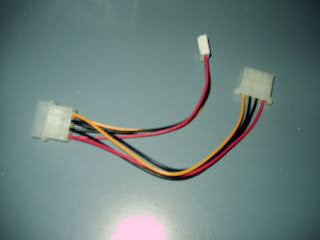
I then used a power Y adapter. This has a male and a female computer power plug, and a small plug for floppy drives.
I cut the floppy drive plug off, I dont need it.
I then cut one of the black wires and the red wire off short. I capped both with heat shrink.
The red and black are +5vdc and ground. My switched power strip has a 12 volt relay, so I dont need the 5 volt leads. I connected the yellow wire to the center terminal of the small jack, and the black wire to the outside terminal. I also soldered a diode across these wires. This is to quench the surge from the relay when it turns off. When current stops flowing through a coil, the collapsing magnetism in the coil generates a reverse current, called Back EMF. This back current can be hundreds of volts. It only lasts for a few milliseconds, but it can damage electronic semi-conductors. I doubt if the computer's power supply would be harmed, but I figure why take the chance? The diode across the leads to the relay will "short out" the back emf, thus protecting the computer. I used one of the 1 amp diodes I bought earlier. (see the load/save entry). The cathode (band) of the diode goes on the yellow wire. (Important.)


I then soldered two wires to the 1/4" jack. This will be for the remote on switch.
I then removed one of the blank PCI slot covers and replaced it with the one I had modified.
I had a spare power plug that I used for the power jack, but if I didnt have one I could have un-plugged the hard drive power plug, plugged it into my Y adapter, then plugged the other plug on the Y adapter back into the hard drive.I then cut two wires going to the computer's power switch. I connected my switch jack into the wires, soldered them, and insulated with heat shrink. This computer, a IBM Netvista, had 4 wires on the power switch. This is the first computer I have seen with more than 2 wires on the switch. There were two yellow and two blacks. I found on the internet that you can splice into either of the yellow and black wires for a remote switch.
So I picked a yellow and black, cut and trimmed them. Then I plugged up the computer and touched the two wires together for a test. The computer came on, so I then turned off the computer, unplugged it from the wall, and soldered my remote switch wires into the circuit.
I soldered the power on switch back in too, so the computer can still be turned on from the front of the computer.

I then replaced the computer's cover.
I now have two extra jacks on the back of the computer. My switched power strip and the "machine on" button on the control panel now have a place to plug into.

On my next entry, I will show how I hacked a cheap power strip to a 12 volt relay.
Note: if you try the above procedures, please make sure your computer is turned off and unplugged. A slip of the hand could short something and cause you a terrible headache.
------------------------

Sunday, May 20, 2007

Coin switch wiring diagram

Here is a schematic of how I wired the coin switches, coin cheat switches, and the cheat disable switch. Click on the picture to enlarge it. Use your browsers "Back" button to return here.


Notice how the micro switches on the coin chutes are orientated differently from the player pushbutton switches? On the coin micros the normally open and normally closed connections are opposite what they are on the pushbutton micros.
Just be sure you wire the switches you have correctly. The switches should have a marking as to which connection is what. Remember that I only use normally open switches on everything on The Rage.